After the whirlwind tour around the world at Music China, The Kakehashi Foundation, Tokyo Gakki Fair and Music Tectonics, The MIDI Association MASSIG was well represented at Audio Developers Conference in Bristol, UK.
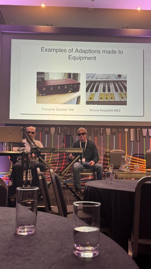
Workshop 5: Interactive Panel: Accessibility in Audio Tech
Tim Yates from Drake Music and Liza Bec discuss the social model of accessibility
13:30 – 17:00 UTC | Monday 10th November 2025 | Bristol 3
As audio production techniques and technologies evolve, so too must the ways we think about accessibility. To improve inclusion in music-making, it is essential that access is evaluated throughout the design of audio technology, not as an add-on or afterthought.
Building on ADC24’s ‘Inclusive Design in Audio Products: Why, Why, How?’ workshop, this symposium comprises a series of sessions that will unpick the systematic barriers to accessibility within audio, and highlight solutions that you can embed into your projects.
Throughout the afternoon, disabled musicians, accessibility consultants, and representatives from organisations driving change will share insights into the opportunities for a more inclusive audio industry. Attendees will help collate a list of inclusive design principles to demystify accessible product development in future.
The concepts covered will be suitable for beginner, intermediate, and advanced audio programmers, though the sessions will not delve too deeply into code examples.
Most of the members of the panel regularly attend the Music Accessibility Standard Special Interest Group of the MIDI Association that meets every week on Thursday morning 8 am Pacific time.
Contributors
Jay Pocknell (RNIB; Sound Without Sight) MASSIG
Liza Bec (Musician; BMV Records)
Mxshi Mo (Musician)
Tim Yates (Drake Music) MASSIG
Tim Burgess (Accessibility Consultant) MASSIG
Tim Adnitt (Native Instruments) MASSIG
Sam Prouse (Accessibility Consultant) MASSIG
David Shervill (Global Music Visions) MASSIG
Building Inclusive Audio Tools: Accessibilitywith ARIA, WCAG, and Real-World Projects
Sam Prouse and David Shervill present about accessibility at ADC 2025
Wednesday 12 November, 09:00 – 09:50 UTC, Bristol 3 and online. Presented by Samual Prouse and David Shervill:
In this talk, Sam and Dave demonstrated how accessibility is not a feature, but a foundation—especially in audio software. Using a mature front-end toolkit and WAI-ARIA (Accessible Rich Internet Applications) attributes, they showed how developers can build interfaces that are both powerful and inclusive, without compromising on complexity or creativity. Drawing from a range of audio projects they have built—synthesizers, sequencers, and sound design tools—they walked through how ARIA roles, properties, and states can be applied effectively. They shared practical examples of making sliders, dropdowns, modmatrices, and other complex UI components screen reader–friendly. The aim is to demystify accessibility and prove it can be integrated from the ground up with thoughtful markup and interaction design.
In addition to implementation, they touched on the broader accessibility landscape, including guidelines from WCAG (Web Content Accessibility Guidelines) and standards from ETSI (European Telecommunications Standards Institute). These provide essential frameworks that help ensure our tools can be used by everyone— including blind and low vision users, keyboard-only users, and others with diverse needs.
Whether you’re building DAWs, plugins, or experimental instruments, this talk will equip you with the knowledge and mindset to make your audio software accessible by design.
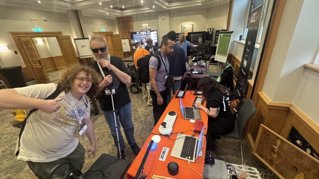
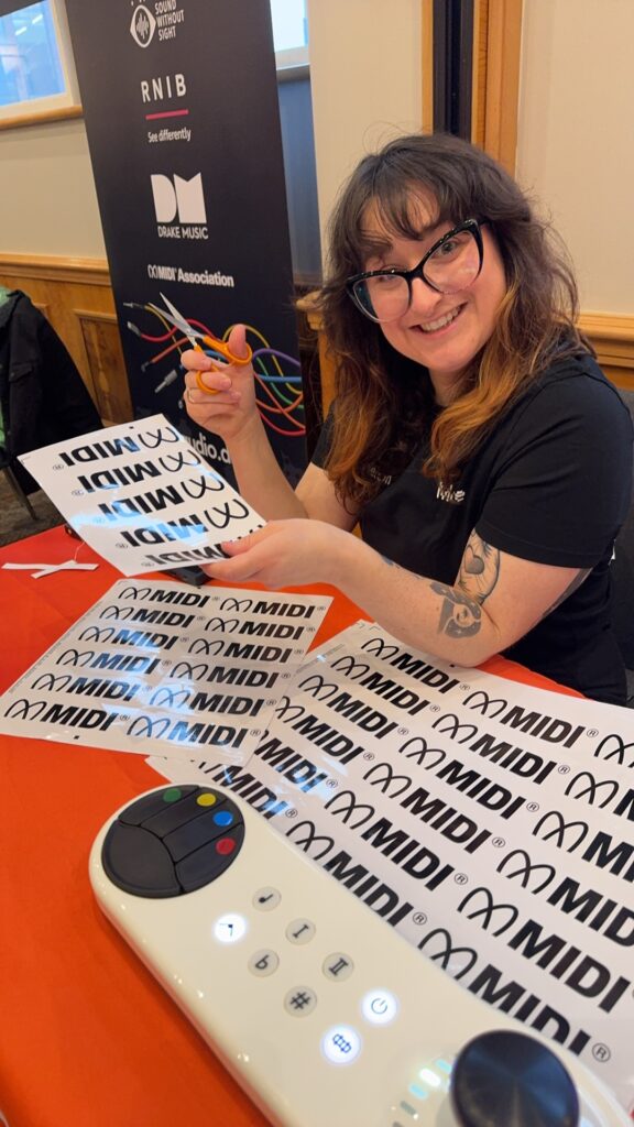
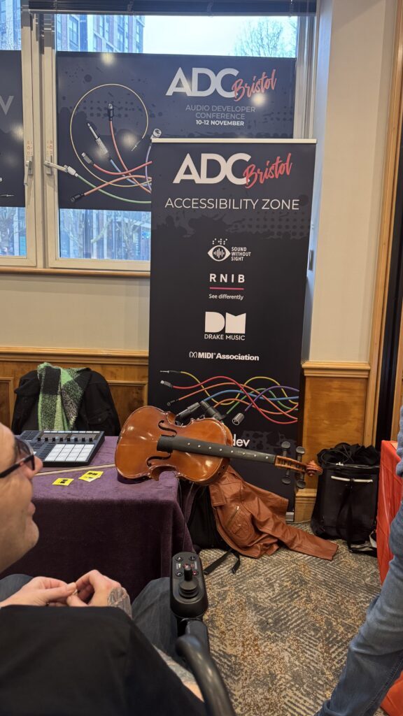
The MIDI Association, Sound Without Sight and Drake Music sponsored the Accessibility Zone at ADC 2025.
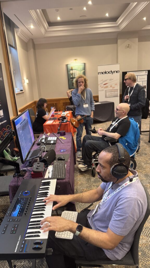
Antony Nasce from 5of12 manned the MIDI Association accessibility table at ADC that featured the same accessible, interactive gear (Connect Through MIDI as the core software connecting up the Arcana Strum, the Oddball, the Cosmos Dots, the Drum Beam) that we had at Music Tectonics , Music China, and Tokyo Gakki Fair.
Adi Dickens, Accessibility Specialist at Ableton
Sound Without Sight and Drake Music had a table right next to us focused on Sound Without Sight’s ongoing efforts to promote accessibility for everyone and Drake Music’s efforts to create an accessible musical instrument collection.
Andre Louis plays the MIDI Innovation Award winner and accessible Native Instruments Kontrol S61 MK3 at Audio Developers Conference 2025
With the introduction of MIDI 2.0 and MIDI-CI there has been an increased use of Manufacturer Id’s, more commonly known as SysEx Ids. Some core mechanisms in MIDI 2.0, including the discovery mechanisms of the UMP Format and MIDI-CI, require the use of a SysEx Id. This was not a requirement in MIDI 1.0.
In 2025 The MIDI Association is introducing significant changes to the way SysEx Ids are handled.
SysEx Ids are now permanent and owned in perpetuity. We no longer require an annual renewal fee.
Any company or entity that is a current MIDI Association corporate member or becomes a corporate member in the future will now own the SysEx Id they are assigned at membership in perpetuity
Any company that has an active SysEx Id listed on the MIDI Association website now owns that SysEx Id in perpetuity
Even those companies that are out of business, or have lapsed their SysEx membership now own the SysEx Ids listed on the MIDI Association website in perpetuity.
The reasons for this change in policy are practical in nature. Interoperability has always been the cornerstone of MIDI. The MIDI Association has never rescinded a SysEx Id and doing so could cause problems even with decades old products in the market.
Where are SysEx Ids used in MIDI 2.0?
MIDI 2.0 requires the use of Manufacturer Ids in several key areas:
MIDI-CI Discovery Messages require the Manufacturer, Family, Model Ids
MIDI-CI Manufacturer defined Profiles
MIDI-CI Property Exchange DeviceInfo Resource declares the Manufacturer, Family, Model Id’s as JSON properties.
UMP Device Identity Notification Message optionally provides the Manufacturer, Family, Model Id’s
UMP System Exclusive 8 uses the 16 bit Manufacturer Id, Special Id 0x7D, or Universal System Exclusive Id in the initial data bytes.
UMP Mixed Data Set uses the 16 bit Manufacturer Id, Special Id 0x7D, or Universal System Exclusive Id.
Note: in MIDI 1.0 byte Streams and UMP, System Exclusive Message payload shall include the Manufacturer Id, Special Id 0x7D, or Universal System Exclusive Id in the initial data bytes.
Which System Exclusive Id should I use?
There are several ways to get a System Exclusive Id for enabling MIDI 2.0 in a product:
Join the MIDI Association. A System Exclusive Id is assigned as a benefit of paid membership.
Purchase a System Exclusive Id from the MIDI Association
The System Exclusive Id 0x7C may be used with the limitations described below.
The System Exclusive Id 0x7D may be used with the limitations described below.
1. Join as Corporate Member
Cost from $600/year
Small to large companies who create and distribute products using the MIDI protocol.
There are significant benefits to being a corporate member:
Unique SysEx Id included
Get access to MIDI 2.0 specifications under development and Member Only developer tools for those new specifications
Have a voice and be a voting member on new MIDI specs
For smaller developers and startups, there is the choice to purchase a non-voting SysEx Id membership that uniquely identifies your MIDI products and lets you do all sorts of creative products with MIDI including MIDI 2.0. https://midi.org/sysex-only-app
3. 0x7C Limited Non-Commercial Id: Products can be released to the Public (Introduced in 2025)
No Charge to Use
Special Id 0x7C is defined by MIDI 2.0 specifications for non-commercial use. Special Id 0x7C Id may be used on any product released to the public, so long as the product does not receive any financial gain either directly or indirectly. Special Id 0x7C may be used only for the following:
UMP Endpoint Discovery mechanisms
MIDI-CI Discovery Mechanisms MIDI-CI Discovery is required for and enables:
Standardized MIDI-CI Profiles
Standardized MIDI-CI Property Exchange Resources
MIDI-CI Process Inquiry
Property Exchange DeviceInfo Resource
The Id shall not be used for any of the following mechanisms:
MIDI-CI Manufacturer defined Profiles
UMP System Exclusive 8
UMP Mixed Data Set
System Exclusive messages with custom or manufacturer defined data format.
Example 1: You are working on a Open Source DIY synth using MIDI-CI Piano Profile hosted on Github and the product is not sold. Example 2: You provide a free software tool for monitoring MIDI Messages.
Devices using this special id are encouraged to enter the MIDI Innovation Awards. This way the MIDI Association, and the world, can see how you use 0x7C to make new and interesting MIDI devices and applications!
4. 0x7D Non-commercial: Products cannot be released to the Public
No Charge to Use
Special Id 0x7D is defined by MIDI 1.0 specifications for non-commercial use (e.g. schools, research, etc.) and is not to be used on any product released to the public.
Example 1: You are working on a one off art project for your own benefit. Example 2: You are researching and prototyping an idea for a school project.
FAQ
Can I upgrade my membership? Yes! For example, it is common for companies that upgrade from being a SysEx Holder to being members.
Can my Manufacturer Id be reassigned? While this may have occurred in the very distant past, MIDI Association does not reassign unused Manufacturer Ids.
Can I transfer ownership of my Manufacturer Id? Yes, However the entity that acquires the Manufacturer Id will need to pay the one off fee again to cover handling costs.
The Universal MIDI Packet (UMP) Format and MIDI 2.0 Protocol introduced Relative Registered Controllers and Relative Assignable Controllers:
Section 7.4.8 of Version 1.1.2 Registered Controller Messages and Assignable Controller Messages directly set the values of the destination properties. With the MIDI 2.0 Protocol’s Relative Registered Controller and Relative Assignable Controller Messages, it is now also possible to make relative increases or decreases to the current values of those same properties. These new messages act upon the same address space as the MIDI 2.0 Protocol’s Registered Controllers and MIDI 2.0 Assignable Controllers, and use the same controller Banks [and Indexes]. However, these Relative controllers cannot be translated to the MIDI 1.0 Protocol.
Data The data field in the MIDI 2.0 Relative Registered Controller and Relative Assignable Controller messages contains a Two’s Complement value, to provide negative and positive relative control of the destination value.
This article uses the term “Relative Controllers” to mean both Relative Registered Controllers and Relative Assignable Controllers.
However, the specification does not provide implementers details of how the data field values are used. The following article provides a set of generic ways for Relative Controllers’ values to be sent from a variety of different physical rotary devices. The receiver does not need to know how the sender is creating a value (or the type of rotary encoder), and the sender does not need to know how a receiver is converting the sent value into a parameter or action.
This work is important to several upcoming Profile specifications. These Profiles will be the first MA specifications where Relative Controllers are defined.
Relative Controllers: How do they work
Relative Registered Controllers (RRC) are an addition to a matched Registered Controllers(RC); the RRC is matched at the same Bank and Index of a RC and adjusts the same parameter on the Receiver. An RRC does not exist without the matching RC.This relationship is the same for Relative Assignable Controllers (RAC) and Assignable Controllers (AC).
The values sent in a relative controllers are not immediately obvious, and can change depending on the type of physical control that is used. A Profile specification might define specific values that should be sent, where it may suggest different values for different encoders.
A Rotary Encoder generally has detents, with most mechanical encoders commonly having 24 detents per 360 degrees.
Figure Example of a Rotary Potentiometer
Like a normal potentiometer, a Rotary potentiometer provides a voltage that is read by an ADC. Unlike a standard potentiometer it rotates a full 360°. Depending on the circuits involved this can have resolutions as high as 1024 steps (or higher) per full revolution.
Relative Controller Values
The value of a Relative Controller is a Two’s Complement value ranging from -2,147,483,647 to +2,147,483,647.
To understand what value we should send we must first look to the matched RC/AC. The RC/AC has a value from 0 to 4,294,967,295. For example: The sender doe not know the current value of the RC/AC. The sender sends an Relative Controller to increase the RC/AC value by 10% (sends 429,496,729). As a result:
Receivers New RC/AC Value = Receivers Current RC/AC Value + 429,496,729.
In other words, we need to send the value of 429,496,729 in the Relative Controller to move the RC/AC value by 10%.
Relative Controller Value Formula for Resolution of the Encoder
If the value being adjusted has a value between 0% and 100%, how many revolutions are required to move from 0% to 100%? An encoder with 24 detents may require a lot more revolutions than a Rotary Potentiometer with 1024 steps.
Step Value = TRUNCATE ( 0xFFFFFFFF / (steps per revolution * rotations) )
If the Rotary Encoder has 24 detents and it takes 8 revolutions to go from 0%-100% then the formula is:
Step Value = TRUNCATE (0xFFFFFFFF / (24*8)) Step Value = 22,369,621
If the Rotary Potentiometer has 1024 steps and it takes 2 revolutions to go from 0%-100% then the formula is:
Step Value = TRUNCATE (0xFFFFFFFF / (1024*2))
Step Value = 2,097,151
Not Sending Every Step
Sending an Relative Controller message for every step when the encoder is moving quickly could very quickly flood a connection, especially if the encoder has a high resolution.
Instead the encoder might use a longer service interval between sent messages, with a cumulation of changes during that interval. For example, the sender’s Rotary Potentiometer above moves 30 steps in a single service interval. Then the sender would send 2,097,151 * 30 = 62,914,530 as the value in the Relative Controller.
Fine Grain Control
Devices often support sending a finer grain control by holding down a button and then sending through a value that is less than the default step value. It is up to the implementation to decide what fraction of the default step value is sent when using a fine grained Relative Controller message.
For example a device with Rotary Encoder that usually sends a step value of 22,369,621. When the user selects fine grain control the device sends 1/100th of each step value. While the “Fine Grain” button is held down, the step value being sent is now 223,696.
Receiver should handle the accumulation of values
Regardless of the value sent, the Receiver of an Relative Controller message should accumulate the values and store them against the local RC/AC value. This avoids situations where receiving a single step value is too small to trigger a change in the parameter value. However, additional step values sent are enough to trigger a change. By using this accumulation method the user does not experience a situation where sending multiple single steps does not move the parameter value.
Step Size vs. Acceleration
Step Size sent is in the domain of the Sender. For example, a Sender might select from 2 values to send: one larger value for each step of the encoder and a smaller value when in Fine Grain mode.
Acceleration is usually in the domain of the Receiver. When the Receiver receives an incoming message, it interprets and implements that change. But if the Receiver receives multiple incoming messages in a short period of time, then the Receiver might implement a larger change for each incoming value.
Bounded Controls vs Non-Bounded Controls
Some properties have clear boundaries of values (such as Min to Max). Such properties are addressable by a Registered Controller or Assignable Controller. Therefore, it may be useful to address the same property in a relative manner.
Some properties or mechanisms are not clearly bound to a fixed range of values (e.g. Scrubbing through a Timeline) and are not easily addressed by a Registered Controller or Assignable Controller. In such cases, it is not appropriate to define a Relative Controller.
Avoid Recording and Playback of Relative Controllers
Recording and Playback of Relative Controllers is problematic because they act upon the current value in the Receiver which can be different at a later time.
For Example: If a Relative Registered Controller addresses the 1′ drawbar to increase its setting by one step, every time the track plays back that drawbar will get louder and louder.
To mitigate against the issue, the recording device should use the Relative Controller value to adjust its known internal RC/AC value.
For Example: A DAW has a plugin in focus and an Relative Registered Controller is attached to edit the plugin parameter controlled by an RC. As the user moves the encoder then the automation lane records the adjusted RC value of the plugin parameter, not the RRC from the sender.
There may be exceptions to this use case and recording Relative Controllers is not prohibited. Relative Controller may exist in an environment where the value should be recorded and sent back to a device that understands the Relative Controller.
When we started working on MIDI 2.0 we knew it would be a long process to rebuild the entire infrastructure that had been built up for MIDI 1.0.
The path to MIDI 2.0
We needed to take the following steps to move MIDI 2.0 forward.
First, we needed a spec on paper which was finished in 2020. But we still had no way to test the ideas in the spec because there was no way to transport MIDI 1.0 and MIDI 2.0 in Universal MIDI Packets (UMP).
We then worked with the USB IF (the group that controls to the USB sepcification and in June of 2020 finished the work on the MIDI 2.0 USB specification. There are now two MIDI 2.0 capable transports – USB and the Ethernet Network transport we finished in November of 2024.
After we had a transport, the work started on getting MIDI 2.0 into the operatinf systems. Apple, Linux and Google have all implemented MIDI 2.0 and Windows is in Developer Preview 8 so will soon be publicly available probably by this summer. Many companies are waiting for the Windows release because they have customers on Mac and Windows.
The next step was support in hardware devices. There are MIDI 2.0 products available from Native Instruments, Roland, Studio Logic, Waldorf and Yamaha. After we had these parts in place we were abel to test and protoype MIDI 2.0 and did some major revisions to the spec in 2023.
We also need support in DAWs and in 2024 we saw MIDI 2.0 support for Logic, Cubase and MultitrackStudio implemented (though in many cases this is a preference setting that you need to turn on).
One of the last steps in this process is determining how DAW plugins will support MIDI 2.0.
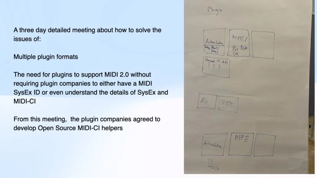
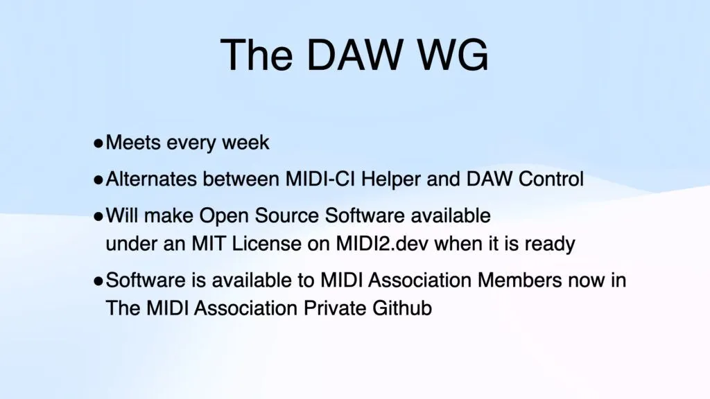
The DAW Working Group
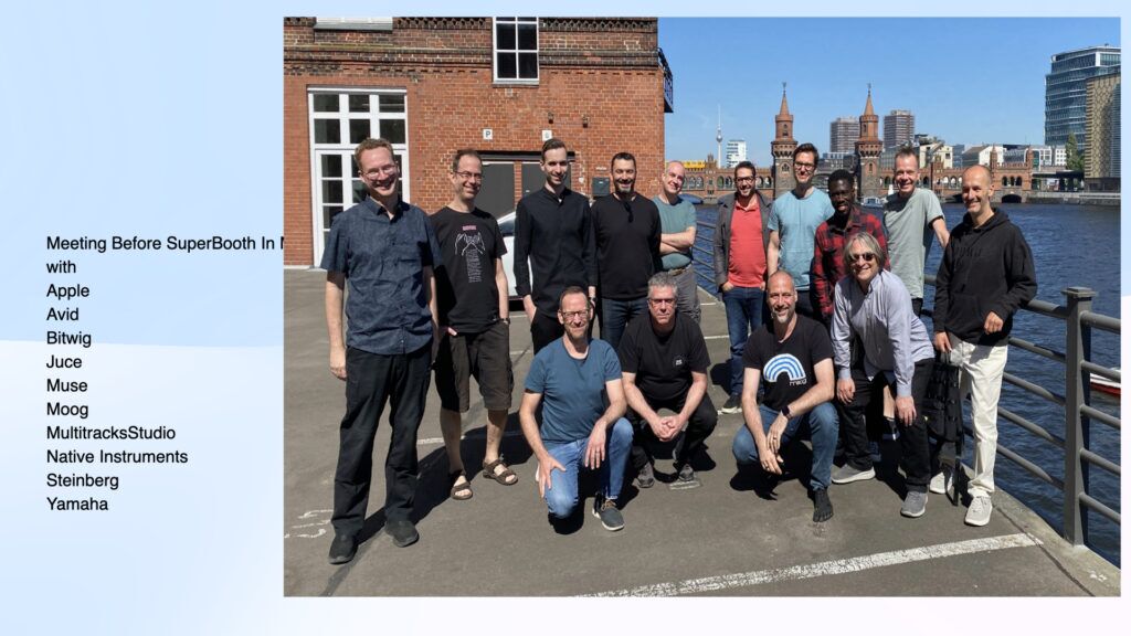
The MIDI Association hosted the first meeting of the DAW working group before Super Booth 2024 at the Native Instruments office in Berlin, where the companies agreed to work together to develop open-source software available under a permissive MIT license to bridge the gap between external MIDI Devices, Digital Audio Workstations (DAWs), and plugins.
We have been meeting every week and continuing our progress.
How to display MIDI 2.0 values
One of the outcomes from the DAW working group is in the article recently posted on MIDI.org about how to display MIDI 2.0 values. This is a great example of how the MIDI Association brings together companies that compete with each other in the market to agree on key concepts so that people who use MIDI won’t be confused by different representations of MIDI 2.0 values.
May 6 and 7 meetings at the Ableton offices in Berlin
This year on May 6 and 7 before Super Booth 2025, we held a very productive two day meeting at the Ableton offices in Berlin. All the plugin format companies (Logic for AU, Avid for AAX, Bitwig for CLAP and Steinberg for VST3) met along with about 20 other MIDI Association and AMEI members to continue the work on the MIDI-CI helper described in this article.
We also are working on a replacement for Mackie and Logic Control that will include a Transport and Location Profile and a new idea discussed at this 2025 face to face meeting for a Dynamic Focus Control Profile -a standardized way to implement some common features in DAWs like Logic’s Smart Controls and Cubase’s Quick Controls. Essentially the idea is to have a group of MIDI 2.0 registered controllers that are dedicated to controlling whatever is in focus in the DAW. The same concept could also be used for plugins in standalone mode and workstation keyboards that often have 8 control knobs that do different things depending on the mode that they are in.
We understand that people are impatient and waiting for the promise of MIDI 2.0 to become a reality. But we also know that we have to carefully plan each step to develop the correct architecture and always ensure the most backward compatibility with MIDI 1.0.
We will soon create an article about MIDI events at Super Booth 2025, but we spoke with hundreds of people at the show and they are all excited (as we are) about what the future holds for the world of MIDI.
MIDI 2.0 Protocol provides many improvements to musicians to help in the creation of music. One of the stand out features is the increase of resolution of MIDI messages from 128 steps to 4.2 billion steps (and 65 thousand for velocity).
This increase ensures that changes in parameters are far smoother and more analogue in their responsiveness.
Note: In MIDI specifications we use hex representations because it can be easier to understand for development. For 32 bit values we use 0x00000000 to represent the smallest value, and 0xFFFFFFFF represents the largest value.
However this huge range presents problems to developers on how to display these values to users. A lot of MIDI 1.0 Devices use 0-127 as the value displayed to musicians, and those musicians are used to seeing and understanding those numbers.
When numbers are much larger it is more difficult to display these numbers to users. For example, is 0x8000000 the halfway point, or is it just 3.1% of the total range of values?*
For more information on converting between different bit sizes and how to handle different resolutions, please see the document MIDI 2.0 Bit Scaling and Resolution.
How to Display Such Large Numbers to a User?
Where possible, the MIDI Association recommends that developers undertake these options in this order:
1. Provide the Interpreted Value to the Musician.
The MIDI Association is working hard to provide ways for MIDI Devices to declare meaningful units and values. For example Profiles and Property Exchange contain methods that declare how a MIDI message value could be represented as a human readable value.
For example, Using the Default Control Change Mapping Profile to understand that Control Change #7 defines the representation of the volume in decibels from -infinity to +0db is more informative than 0x00000000 to 0xFFFFFFFF.
2. Display 0% – 100%
When a unit and value is unknown it is often acceptable to use percent values [0% .. 100%], or to use [-100% .. 100%] for bipolar values if applicable.
As a developer you may decide how many decimal places are best suited for your display.
3. Display 0.00 – 1.00
Similarly to the previous option, when a unit and value is unknown it is often acceptable to use floating point [0.0 .. 1.0], or to use [-1.0 to 1.0] for bipolar values, if applicable. This is more inline with the internal values used in plugins.
As a developer you may decide how many decimal places are best suited for your display.
4. Display 0 – 127 with decimal places
If the previous options do not suit and you must display MIDI 1.0 like values, or if you need to display values where the MIDI device is working in both MIDI 1.0 and MIDI 2.0 Protocol environments; then the 32 bit value should be treated as 7.25 fixed point values.
This means the value being visualized starts at 0 and approaches (but not reaches) 128.
In doing this the precise center value (0x80000000) is maintained and translation between MIDI 2.0 and MIDI 1.0 Protocol results in the expected value being sent to MIDI 1.0 devices.
In order to visualize the absolute minimum value (0x00000000), the absolute maximum value (0xFFFFFFFF) and the precise center value (0x80000000) one should use symbolic values “MIN”, “MAX” and “MID”. This ensures that these special values can be differentiated from values being very close to them (0.00000001 rounded to e.g. 0.000, 63.9999999 rounded to e.g. 64.0, 127.9999998 rounded to e.g. 127.999).
C++ Example of a function to display these values:
template <typename T>
std::string hirezRepresentationString(T value, uint32_t decimalPlaces)
{
   constexpr int numBits = sizeof(T) * 8;
   constexpr int fractionalBits = numBits - 7;
   constexpr T maxVal = std::numeric_limits<T>::max();
   constexpr T midVal = (1 << (numBits - 1));


   if (value == 0) {
       return "MIN";
   }


   if (value == midVal) {
       return "MID";
   }


   if (value == maxVal) {
       return "MAX";
   }


   const auto hiRezValue = static_cast<double>(value) / static_cast<double>(1 << fractionalBits);
   const auto formatString = std::format("{{:.{}f}}", decimalPlaces);
   return std::vformat(formatString, std::make_format_args(hiRezValue));
}
Note that this code works up to 6 decimal places. However, this is more than enough for most applications.
The MIDI Association has made significant progress this year in developing two Profiles focused on electronic drums and drum machines.
The Default Drum Map Profile defines a MIDI-CI Profile for a default mapping of specific drums to specific Note Numbers. The note map used in this Profile was established by many products in the 1980s as a commonly used set of note assignments for drum sounds and that was later standardized in General MIDI.
Many drum machines, grooveboxes, keyboard workstations, portable keyboards, digital pianos, and software synthesizers (many of which do NOT support the full GM specification) have drum kits that utilize this drum kit mapping because of the vast quantity of MIDI data available that will play properly with these drum maps.
Electronic Drums are one of the most successful categories of MIDI instruments.
Most electronic drums from different manufacturers share a common set of features (standard MIDI messages including velocity, pan,etc.) as well as more drum specific features (choking of cymbals, positional sensing of cymbals and drums, etc). However, the MIDI messages used to control these features have not been standardized and mainly rely on manufacturer specific SysEx. A MIDI-CI Profile would define far greater interoperability, unifying the industry behind a common set of MIDI messages.
Steve Fisher- Director – Drums Product Development Medeli
Ben Israel- Research and Content Design Manager -Yamaha
Mike Kent- Chair of MIDI 2.0 WG/MIDI Association Executive Board.Drum Profile Chair Co Founder Amenote
Mike Snyder -Innovation Manager, Electronic Instruments at Avedis Zildjian Company
Ikuo Kakehashi- Founder of BAC Audio a team of master electronic instrument engineers who worked on Zildjian’s new ALCHEM-E series electronic drum kits
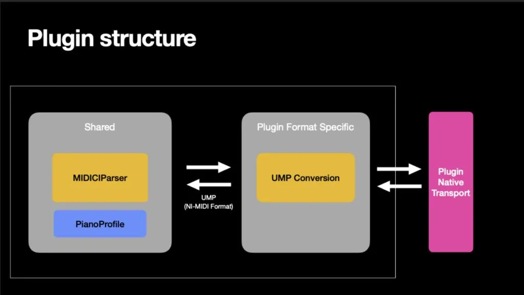
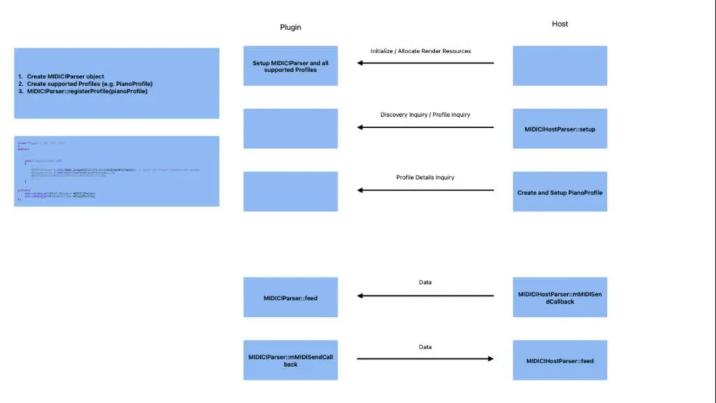
The MIDI Association member companies that develop plugin formats – Apple (Audio Units), Avid (AAX), Bitwig (CLAP) and Steinberg (VST) are working together to develop open-source software that will enable plugin developers to quickly and easily interface with external MIDI gear without the need for any in depth knowledge of MIDI 2.0 or MIDI-CI. Another MIDI Association member supporting this effort is JUCE – the most widely used framework for audio application and plug-in development.
The MIDI Association DAW working group is creating open source software that will look at MIDI 2.0 messages from external devices, extract the information the plugin needs to support Profiles like the Orchestral Articulation, MPE and Piano profiles and translate those MIDI messages into the native plug formats that plugins already understand.
By utilizing this open source software, plugin companies can start supporting MIDI 2.0 external devices with minimal development costs.
Before Super Booth in May of 2024, The MIDI Association hosted the first meeting of the DAW working group at the Native Instruments office in Berlin, where the companies agreed to work together to develop open-source software available under a permissive MIT license to bridge the gap between external MIDI Devices, Digital Audio Workstations (DAWs), and plugins. That cooperative project is ongoing in the MIDI Association’s DAW Working Group.
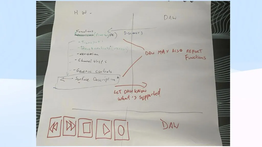
The DAW Working Group is also working on a DAW Control Profile which would supersede proprietary control protocols like Mackie Control and Logic control with a true industry standard for controlling DAWs via external hardware and software.
The MIDI Association and its members provided updates on the latest developments in the major operating systems at Winter NAMM 2025.
Microsoft announced updates to both MIDI and Audio at the Qualcomm Snapdragon Summit 2024 including better APIs which support MIDI, including MIDI 2.0 and full support for low-latency, high-channel-count audio, using standards already accepted by the industry.
Apple, Google and Linux are all continuing their MIDI 2.0 updates to support new MIDI Association specifications.
If you are a developer of MIDI products, this is a presentation you won’t want to to miss.
Pete Brown also provide more details about the Windows Customer Preview available in this article.
In our NAMM wrap up , we reported on all the exciting things that are happening in the world of MIDI 2.0.
Today is a major step in the adoption of MIDI 2.0 as Microsoft has just announced release of their first public version of their new Windows MIDI Services.
Today, we’re releasing the latest version of Windows MIDI Services to the Windows Insider Canary Channel, fully enabled for anyone to evaluate. We recommend this for technical users (as with any Canary release) and not for production use because we will have bugs.
The Windows Insider blog post details what’s in this release and in the associated Windows MIDI Services App SDK. Here are some more details.
The Windows Insider Canary Channel is provided for testing and evaluation on non-production PCs. Please see the Windows Insider blog post for additional information about the Canary Channel.
What’s in the box? This Windows Insider release includes our new MIDI 2.0 and MIDI 1.0 class driver (kindly funded by AMEI and developed by AmeNote in partnership with Microsoft), the WinMM (MME) redirection driver and code, and the new Windows Service and its transport and transform plugins. It includes everything you need to be able to try existing MIDI 1.0 apps and devices, and to verify that they work as expected. It’s representative of how we’ll ship in mainstream Windows later this year.
MIDI 1.0 benefits with this release: Every MIDI device is now multi-client, even for existing applications and devices. You do not need vendor drivers to enable more than one application to use a MIDI device. MIDI Port names are now better. We’ve surveyed many MIDI devices in market and come up with algorithms which provide better port and endpoint names for these devices. But there will always be exceptions. If you see those, please report them to us on GitHub (developers) or on our Discord Server (everyone else) Devices using the new USB MIDI 2.0 Class driver have faster data transfer. The USB MIDI 2.0 class driver uses faster data transfer mechanisms even for MIDI 1.0 devices. (If your MIDI 1.0 device is not picked up by the new driver, and is class-compliant, you can manually assign usbmidi2.sys to the device. We’ll post instructions for this in the future) The new features are backwards compatible with your existing apps and devices USB MIDI 2.0 devices and USB MIDI 1.0 devices are both usable from the WinMM (MME) APIs in a MIDI 1.0 capacity.
Everything here works on Intel/AMD x64 as well as Arm64 devices
Here’s the WinMM backwards-compatibility in practice. Most apps you have today using WinMM MIDI 1.0 will work with the new service. If you find apps which do not, please do let us know (see how to report bugs/info below)
Pete Brown
Microsoft and MIDI Association Executive Board Chair
Special thanks to Microsoft, Amenote and AMEI (the Japanese MIDI Association) for their ongoing support of our efforts to improve the way musicians make music digitally.
User Datagram Protocol for Universal MIDI Packets (aka Network MIDI 2.0) defines a standard way to connect MIDI devices (MIDI 1.0 and MIDI 2.0 protocol) via Ethernet and wireless LAN. The initial version was ratified by the MIDI Association and AMEI in November 2024.
Ethernet and wireless LAN are suitable transports for MIDI. They complement, and can sometimes replace, established MIDI transports like 5-Pin DIN and USB MIDI.
Highlights:
Long distance
Ethernet cables can transmit data up to 100 meters (330ft) without any signal loss or degradation.
Wireless can reach up to 45m (150ft) with direct line of sight (actual distance depends on a number of factors)
Low latency
Typical latency on Ethernet is under 1ms. Wireless LAN latency depends on connection quality and technology, but typically under 5ms.
High bandwidth
100MBit/s or more on Ethernet, 1MBit/s or more on wireless LAN
One cable/wireless link is enough for many logical connections
Ground isolation
On Ethernet, connections are electrically isolated, reducing the chances of electrical grounding noise issues.
Auto-Discovery
Can select devices to connect by name
Off-the-shelf parts and infrastructure
Standard cables (Cat5, Cat6, etc.), routers, switches, and components are readily available and cost effective
Many transports for audio already use Ethernet or IP-based protocols. Some of those are open standards (i.e. AES67) and some are proprietary. Being able to run MIDI 2.0 as a control protocol over the same links that run audio can greatly expand the use of MIDI 2.0.
Wireless MIDI 2.0 using Wireless LAN
The same protocol can be used on wired connections via Ethernet, and wireless connections on wireless LAN, also in mixed environments.
Logical connection setup (Session Management)
The user has full control over which device is able to send/receive MIDI with which other device (or application)
Connections can be changed without having to move physical cables.
Many MIDI streams (sessions) can be configured on the same cable
Simple security mechanisms available in Network MIDI 2.0 help prevent unauthorized access
Peer to peer connection is possible without the need to route data through a computer.
Software implementations do not require OS support
Example of a networked MIDI studio:
Who can take Advantage of Network MIDI 2.0?
Every MIDI user can benefit of Network MIDI 2.0: it provides a bridge between MIDI 1.0 and MIDI 2.0 devices.
Although Network MIDI 2.0 is particularly well suited as a MIDI transport, other transports like USB-MIDI 2.0, and the good old MIDI 5-pin DIN, have their own merits. Therefore, Network MIDI 2.0 is just one more transport for MIDI.
Who’s In? Network MIDI 2.0 at NAMM 2025
The first products which use this specification are starting to be released and will be featured at The MIDI Association booth 10302 at the front of Hall A at the 2025 NAMM show.
Examples for announced or available products with Network MIDI 2.0:
Which Devices and Applications can use Network MIDI 2.0?
To add Network MIDI 2.0 in support to your device, the requirements are reasonably simple. First, there are the physical components (connector, transformer, …). Secondly, the software implementation needs to provide IP and UDP functionality, plus the implementation of the Network MIDI 2.0 protocol itself. The standard is designed with the goal that even systems with little memory will be able to implement the minimum required set of Network MIDI 2.0 features.
Software applications can implement the Network MIDI 2.0 standard using OS provided APIs for IP and UDP functionality. However, we expect availability of general-purpose Network MIDI 2.0 connector applications, and OS components and APIs, so that most applications do not need to implement the Network MIDI 2.0 standard on their own. Remote MIDI devices may be used the same as locally connected MIDI devices.
Version 1.0: Simplicity
The first version of Network MIDI 2.0 was developed with the goal of providing an easy to use and easy to implement solution. Only essential features are specified. The specification is limited to Local Area Networks using wired Ethernet and wireless LAN. Data transfer uses UDP as the underlying protocol.
However, the standard is extensible, so we may see updated specification versions with additional, backwards compatible, functionality.
Three Sections
The standard is divided into three sections:
Section 1: Discovery
Who’s out there?
Section 2: Session
Connection setup and tear down
Section 3: Data I/O
Send and receive UMP
Let’s start with a description of the first section.
Section 1: Discovery
The discovery allows a device (or application) to find other Network MIDI 2.0 devices (hardware or software applications) which are reachable via the network.
User Friendly
Discovery allows users to select MIDI device(s) to connect to by name. Imagine a keyboard with a display, where you have a list of synthesizers in your studio, and you just select the one you want to play… done!
Using Established Standards
Network MIDI 2.0 discovery uses the established standard mDNS with DNS-SD. This standard is also known as “ZeroConf networking” and as “Apple Bonjour”. This allows devices to advertise their MIDI 2.0 services using the publicly registered service type: “midi2”. This discovery allows mDNS/DNS-SD devices to get the following information about a Network MIDI 2.0 device:
IP Address
UDP Port
UMP Endpoint Name*
Product Instance Id*
*These properties are defined by MIDI specifications.
Operating System Support
Common operating systems already provide mDNS services for use by applications, so it is simple to add Network MIDI 2.0 Discovery to your implementation.
Optional
Network MIDI 2.0 Discovery is optional. But we highly recommend implementing it in your device. Otherwise, your users won’t be able to select your device by name!
Some special devices may not need Discovery. For example, in some systems a device will need to be hard wired somehow (using a fixed IP address), where such auto-discovery wouldn’t make much sense.
Section 2: Session
The Session section is all about (logical) connections of Network MIDI 2.0 devices. The term Session is used here, because the word “connection” could mean many other things, too.
The Session functionality is required for all Network MIDI 2.0 devices, because plugging an Ethernet cable into a network does not tell the device with which other MIDI device you want to be “MIDI connected”.
Client and Host
In Network MIDI 2.0 terminology, a Client starts a Session with a Host. A typical scenario is that the Hosts advertise their Network MIDI 2.0 services via Discovery, and the Client selects a Host, then starts the session with it. Of course, a single device can assume both Client and Host roles for different Sessions. In fact, we expect that most devices and applications will be both Host and Client (i.e. they’re discoverable, and they can initiate a Session).
Session Commands
The Network MIDI 2.0 Session specifies different Session Commands for starting a Session (Client), accepting a Session (Host), and terminating a running Session (both Client and Host).
Under the hood, the Session Commands are plain UDP messages with a short, simple header which specifies which MIDI-specific Session Command is being sent.
Authorization
The two-step Session setup allows devices (in Host role) to ask the user to acknowledge an incoming Session request. This is useful for devices with public access, or where you don’t want random people to play your synth via the network.
Authentication
Additionally, the Session specification also provides mechanisms to secure a Session with a password or PIN for a successful Session initiation, or to provide a valid user+password combination.
Note that the Authentication mechanisms currently provided in Network MIDI 2.0 only provide simple security and do not use any encryption. But they are simple to implement, and do provide a minimum level of security.
These Authentication mechanisms are optional. But keep in mind that a Host may require Authentication: in that case, your Client will only be able to connect if it can provide the Host with a matching password or username + password. In general, though, we recommend that a Host can be configured to require Authentication or not.
Multi-Session
The Network MIDI 2.0 standard allows very flexible session configurations. Examples:
One Client can connect to multiple Hosts
One Host can accept Sessions from multiple Clients
A device can use multiple Client instances for multiple Sessions to the same Host
A device can also have multiple Hosts, e.g. for separate logical units (although, because we’re sending UMP, separate Groups can be used for that).
Handling Command Packet Loss
Because UDP does not guarantee packet delivery, the Session protocol is designed to gracefully handle a lost Session Command. Most Session Commands (like the Invitation Command to request the start a Session) are repeated until a reply is received. During that time, the Command is pending, and can be terminated by the user, or if a time-out occurs (depending on the implementation).
To further check that a remote Host is still alive, the Ping Command can be used. The remote Host will reply with the Ping Reply Command if it is still powered on and connected to the network.
Section 3: Data Transmission
The third section of the Network MIDI 2.0 specification is all about sending and receiving MIDI messages in the Universal MIDI Packet data format (UMP). As you know, UMP can contain messages in MIDI 1.0 protocol and in MIDI 2.0 protocol.
Session Established: Can Send and Receive UMP
Once the Session is established, both Host and Client can send and receive UMP, where the full UMP feature set is available. The Network MIDI 2.0 layer is agnostic to the UMP contents: any UMP packet will be transmitted. The Network MIDI 2.0 layer never creates or consumes UMP messages, and there is no need for the (deep) inspection of the UMP data.
Multiple Commands per UDP
For sending UMP, the UMP Data Command is used. Because it uses the same header as Session Commands, you can mix and match Session Commands with UMP Data Commands in one UDP packet for efficient transmission. The flexible Command allows multiple UMPs in one UMP Data Command, and multiple UMP Data Commands per UDP packet.
Data Integrity: Sequence Number
Every UMP Data command has a sequence number. It allows receivers to detect:
out-of order packets
missing packets
duplicate packets
Data Integrity: FEC
Forward Error Correction (FEC) is a simple mechanism to recover from occasional loss of a packet. Remember, UDP does not guarantee delivery of packets…
The idea of FEC is that when a sender sends UMP data in a UDP packet, it routinely includes the two most recent UMP Data Commands in the same UDP packet. So from the point of view of the receiver, if one UDP packet gets lost, the receiver will get the missing UMP with the next UDP packet. Receivers, on the other hand, always discard UMP Data Commands with a sequence number they have already processed. Because the FEC Data Commands have previous sequence numbers, receivers will usually ignore the additional FEC Data Commands.
Because FEC has very low requirements for both senders and receivers, it is highly recommended that all devices implement FEC.
FEC can also be combined with the following mechanism for even higher data integrity.
Data Integrity: Retransmit
If the local device discovers a missing packet (and FEC does not fix it), a Retransmit can be requested from the remote device. If the remote device keeps a Retransmit buffer, it can resend the missing packet. Otherwise, it notifies the local device via a Retransmit Error Command that the buffer does not contain the missing packet.
Retransmit functionality is optional for both sending and receiving side. If a device does not keep a retransmit buffer at all, it will respond with a NAK Command when it receives a Retransmit request. That’ll let the other device know that there is no point in further trying Retransmit.
Ethernet Packet Format for Network MIDI 2.0
Network MIDI 2.0 compared to RTP-MIDI
Network MIDI 2.0 (UDP) defines a standard method to transport MIDI 1.0 and MIDI 2.0 messages in the Universal MIDI Packet format. Network MIDI 2.0 (UDP) was published in 2024 as a specification of the MIDI Association. A few compatible devices will be available in 2025, with growing adoption in the years ahead.
RTP-MIDI was created by independent developers to define a method to transport MIDI 1.0 messages. RTP-MIDI was published by IETF as an RFC in 2006. RTP-MIDI is implemented in Apple operating systems (as “Apple MIDI”), as independent drivers for Linux and Windows, and in various MIDI devices.
The Network MIDI 2.0 (UDP) is expected to garner higher adoption and will eventually will largely replace RTP-MIDI for many devices and applications.
COMPARISON
RTP-MIDI
NETWORK MIDI 2.0
Official MIDI Association Specification
No
Yes
MIDI 1.0 Support
Yes
Yes
MIDI 2.0 Support
No
Yes
Universal MIDI Packet Support
No
Yes
Error Recovery
Optional journalling system (missing in most implementations and known to have bugs where implemented)
Bonjour / mDNS+DNS-SD: “_apple-midi”, not part of RFC specification
Included: mDNS+DNS-SD: “_midi2”
Specification: Session
Apple proprietary, documented
Included
Specification: Message I/O
RFC / IETF for MIDI
Included
Packet Retransmission in the Case of an Error
No
Optional retransmit functionality defined
Device Capabilities Identification
No
Yes, by standard UMP messages
Jitter Reduction Timestamps
Only on transport level, timestamps rarely supported. Poor implementations exist
At the UMP layer (end-to-end), using Jitter Reduction Timestamps
Timestamping Resolution
100us
32us
Resources Needed Per Endpoint
2 UDP ports
1 UDP port
Compatibility with Microcontrollers
Not part of the original protocol design
Designed with microcontrollers compatibility in mind
Operating System Support
Only officially supported by Apple OS’s (macOS, iOS, iPadOS). Third party drivers are available for Windows and Linux.
Microsoft has announced official support pending for Windows. ALSA is currently adding support for Linux. All applications can connect via standard networking on Android, MacOS, and iOS.
Possible Future Plans
The MIDI Association has tried to keep the standard simple. To better clarify the scope of the current version, here are a few features that are not in the initial version but might be added in future expansions of the specification.
Encryption
Network MIDI 2.0 does not provide any encryption of the UMP data (or of the Session Commands). If encryption is required, it can be configured on a lower layer, for example with a VPN or an encrypted tunnel. This is currently outside the scope of the Network MIDI 2.0 standard.
Clock or Synchronization
In the first version, the Network MIDI 2.0 standard does not define any mechanism for time synchronization. Clock and synchronization mechanisms are available on the UMP layer, e.g. JR Timestamps or MIDI 1.0 clock.
Remote Session Management
Version 1.0 of the Network MIDI 1.0 standard defines Session management between pairs of devices (“device A with device B”). Remote Session management would allow device A to tell device B to initiate a Session with device C. Such functionality would be useful for central studio and stage management.
There is no defined method to do this at this time, but the MIDI Association sees a lot of value in remote Session management and may add it to the standard in a future revision.
Interested in adding Network MIDI 2.0 to your products
We’d love to hear from you if you’re interested in adding Network MIDI 2.0 to your product, or if you have any comments!
The MIDI Association is working on a series of articles for assisting you with the implementation of the Network MIDI 2.0 standard into your product. You can sign up to receive notifications here:
Developer Design Options for Devices based on MIDI-CI v1.2
by Andrew Mee and Mike Kent
MIDI-CI defines how a device can use a bidirectional connection to discover details of another device. In some cases a device might be connected to more than 1 other device which also uses MIDI-CI.
This article discusses device design strategies for handling MIDI-CI functions when the current connections are more than one to one. For this purpose we present two terms which are not defined by MIDI-CI but used only to explain design strategies in this article.
Session: A binding between 2 devices created by ongoing communication of MIDI-CI Transactions. Generally established while using a Profile, a PE Resource, or a Process Inquiry.
MIDI-CI Instance: Inside a MIDI device, a set of information stored about another connected MIDI-CI device, with the MUID of the connected device as the core property.
A Session often requires a MIDI-CI Instance in the Initiator and sometimes in the Responder.
MIDI-CI defines that a Transaction is an inquiry sent by one MIDI Device and a reply returned by a second MIDI Device. Single Transactions do not establish any kind of Session. Therefore, and in most cases, the following Transactions do not require a MIDI-CI Instance in a device.
Discovery
Profile Inquiry
Inquiry: Property Exchange Capability
Inquiry: Process Inquiry Capability
Some MIDI-CI mechanisms rely on an ongoing set of Transactions. These mechanisms probably require a device to consider those mechanisms as establishing a kind of Session between two devices. One or both devices might require an internal MIDI-CI Instance. Such mechanisms are:
When 2 Devices agree to use Process Inquiry, the Initiator usually creates a MIDI-CI Instance. The Responder may not need a MIDI-CI Instance.
When two Devices agree to use a Profile, the Initiator usually creates a MIDI-CI Instance. The Responder may not need a MIDI-CI Instance.
When 2 Devices agree to use a Property Exchange Resource, the Initiator usually creates a MIDI-CI Instance. The Responder usually only needs a MIDI-CI Instance if it agrees to serve subscriptions.
Do Not Create a MIDI-CI Instance Unless Necessary
Note: Devices should send the associated reply to these inquiries, even if the Device cannot create a new MIDI-CI Instance:
Discovery -> Reply to Discovery
Profile Inquiry -> Reply to Profile Inquiry
Inquiry: Property Exchange Capabilities -> Reply to Property Exchange Capabilities
Inquiry: Process Inquiry Capabilities -> Reply to Process Inquiry Capabilities
Inability to create a new MIDI-CI Instance should not cause sending a NAK. (There may be other reasons to reply with a NAK.)
Sending a reply to these inquiries only requires the Responder to store information about the inquiry, including the MUID address of the Initiator, until the Responder has sent a reply.
Example Implementation Scenarios for Devices with Limited Resources
Some devices have limitations of memory and processing power. Typically, hardware devices have more limitations than software applications running on a computer. Following are 2 examples of potential issues, each with several proposed solutions. Some of the solutions provided are for normal MIDI-CI mechanisms, but some are provided to deal with error cases such as a device which becomes disconnected without sending an Invalidate MUID message.
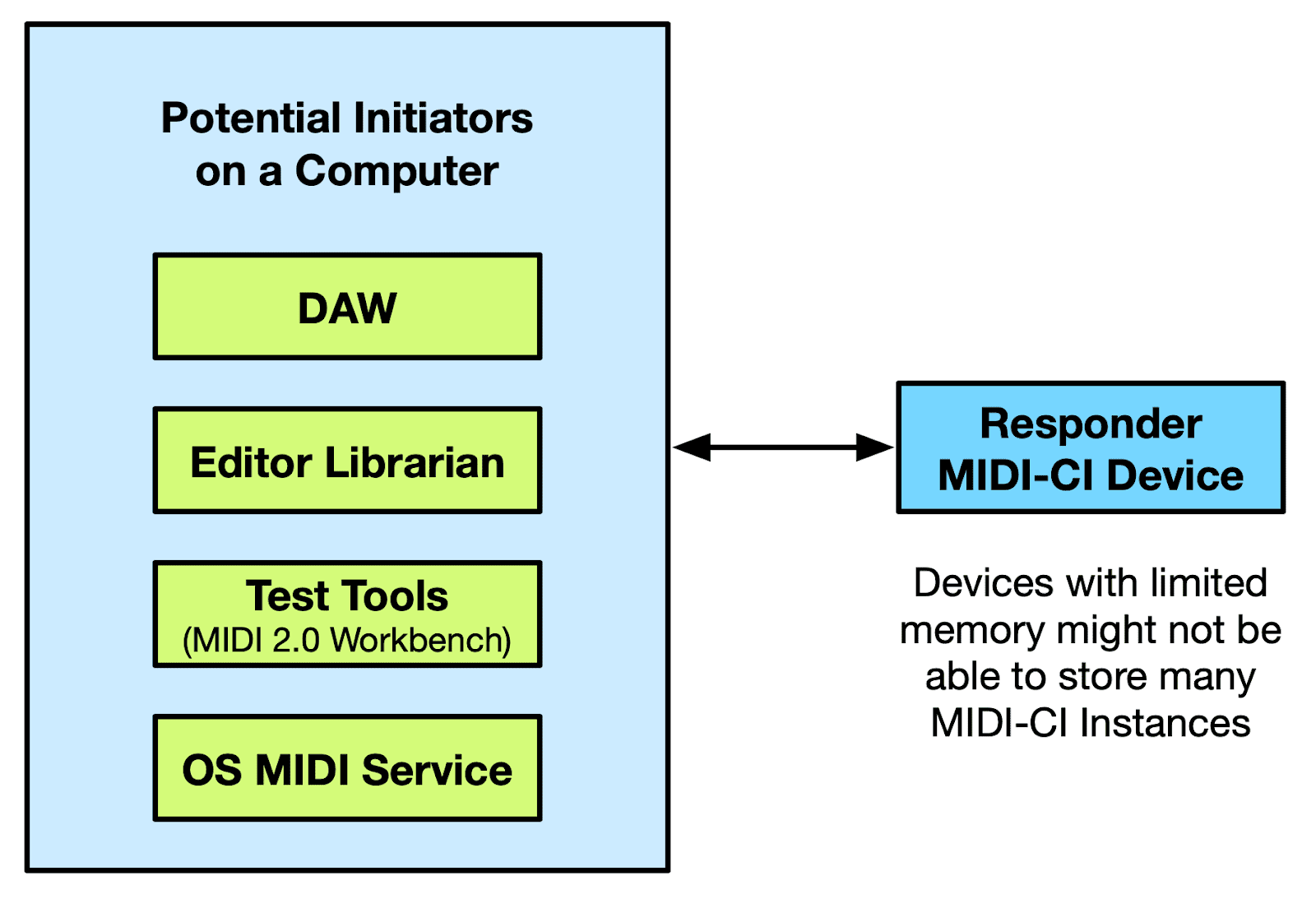
Example 1: Responder Device Restricted to Supporting Single MUID
In this example, a limited hardware device which acts only as a Responder is connected to a computer with the potential for multiple MIDI-CI Initiators. The Responder only has enough memory to store a single MIDI-CI Instance.
There are potential issues which could occur:
If the Responder creates a MIDI-CI Instance for the first Initiator which requests a connection, that could “lock” the Responder against other MIDI-CI Instances. The Responder might NAK other Initiators. The Responder may not be able to determine that a different Initiator is preferred.
If an Initiator “goes away” without sending invalidate MUID, Responder is unable to see that Initiator no longer exists. i.e. no clean-up
Responder has limited methods to verify Initiator still exists.
Responder Solution 1: Device Does Not Create a MIDI-CI Instance to Store Initiator MUID/Info
A simple MIDI-CI Device (with restricted memory), acting as a Responder, probably does not need to store the Initiator MUID and associated information. Instead, Responder might:
Respond to request from the Initiator using the Source MUID from the request as the Destination MUID in the reply. Then forget the MUID of Initiator.
Only Send out Notifications using the Broadcast MUID. e.g. Profile Enable Message.
Responders using this method do not need to track active status of Initiators. No MIDI-CI Instance has been created so no “clean-up” needed.
Note: This solution is not applicable in a few cases (because in these cases the Responder probably needs to create a MIDI-CI Instance):
The Responder wants to accept Property Exchange Subscriptions requests.
An active Profile requires the Responder to send notifications to an Initiator using a non-Broadcast address.
The Responder is expected to make a Profile Details Inquiry of the Initiator more than once after a Profile is enabled.
More than 512 bytes of Sysex data is needed to be sent on any given MIDI-CI message.
However, many Responders will work well without any of the mechanisms listed above.
Responder Solution 2: Device Only Stores Minimal Initiator Information When Absolutely Needed
Responder should only store the data which is absolutely needed for each MIDI-CI Instance. There is a lot of data provided in MIDI-CI messages, much can be “thrown away”. Some examples of data which might not need to be stored:
Manufacturer, Family, Model Id’s, and Version are often not needed.
Devices that are only working with Profiles do not need to store PE data.
Max Sysex only important if you are going to use messages greater than 512 bytes
A clean-up mechanism to remove inactive MIDI-CI Instances should be considered when this solution is used.
Example Device: The MIDI Association developed a prototype to test and demonstrate Property Exchange. The device has a total memory of only 96Kb. The device only creates a MIDI-CI Instance when a Subscription is requested. When a change occurs, the device looks through the list of MIDI-CI Instances to find current subscription(s), and sends out the Property Exchange Subscription notification. If Property Exchange Subscription Notification is sent and no Reply to Subscription Message is received, a clean-up process is initiated for that MIDI-CI Instance.
This method keeps memory use to a minimum. This prototype can manage 25 unique Subscriptions in fixed memory, using less than 256 bytes.
Responder Methods of “Clean-up”:
Do Not Create MIDI-CI Instance – no need for clean-up (suitable for many devices but not in all situations, see Responder Solution 1)
Use MIDI-CI Messages sent directly to Initiator (not Broadcast) and check for Reply. If there is no reply then it can be considered inactive and removed from memory.
Resend Discovery. If an existing Initiator does not respond it can be considered inactive and removed from memory.
Receive Invalidate MUID message containing Initiator MUID.
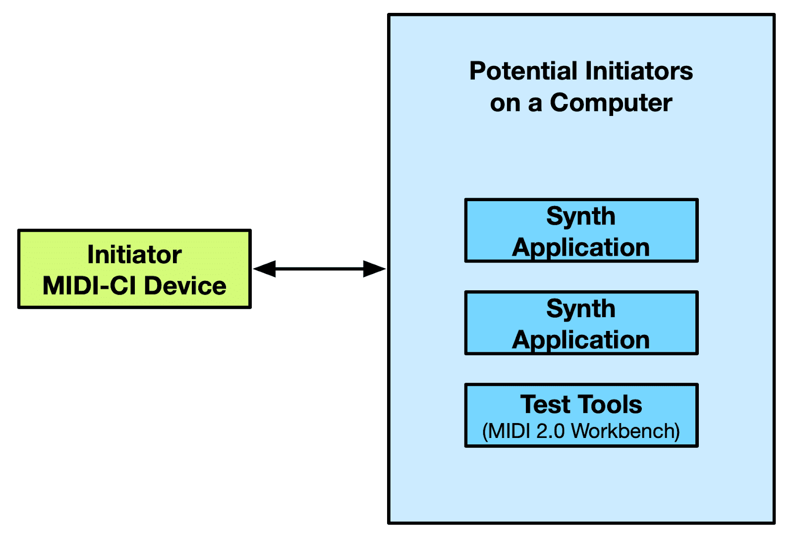
Example 2: Initiator Device Discovers many Responders available for Communication
In this example, a limited hardware device which acts as an Initiator is connected to a computer with the potential for multiple MIDI-CI Responders. The Initiator has limited memory for MIDI-CI Instances.
There are potential issues which could occur after the Discovery Transaction:
The Responder may already have a MIDI-CI Instance for another Initiator (this may include inactive Initiators) and may NAK a new Session.
The Initiator may have “choice paralysis”, as such the Initiator may have difficulty automatically deciding which Initiator is best for the user.
The Initiator may be unaware if a Responder disappears in the future.
Solution: Initiator and Responder Implementations
Responder
Should support multiple Initiators. As Responder is on a computer, memory for multiple MIDI-CI Instances is not an issue.
Initiator
Offer a choice to the user for selecting which Responder to communicate with.
Use Clean-up methods (below) to remove inactive Responders.
Initiator Methods of “Clean-up”:
If the device receives an Invalidate MUID message containing Responder MUID, then remove the MIDI-CI Instance.
Resend Discovery to confirm that the Responder is still active. If a prior existing Responder no longer replies, the Responder can be considered inactive and removed from memory.
A Session and MIDI-CI Instance are usually needed to work with a Responder for one of 3 “P”s: Profile Configuration, Property Exchange, or Process Inquiry. Send a Profile Inquiry, PE Capabilities, or Process Inquiry Capabilities message periodically as a “Ping” to confirm that the Responder is still active.
Note: There is usually no need to create a MIDI-CI Instance for any device which does not support one of the 3 “P”s.
Pete Brown is both the MIDI Association Exec Board Chair and a Principal Software Engineer in the Windows Developer Platform team at Microsoft. He focuses on client-side dev on Windows, apps and technology for musicians, music app developers, and music hardware developers, and the Windows developer community.
For musicians, there are two key enabling technologies for making music – MIDI and Audio. Microsoft announced updates to both are coming soon to Windows.
Microsoft announced updates to both MIDI and Audio at the Qualcomm Snapdragon Summit 2024.
What did we announce today for musicians and other audio professionals?
Musician Software coming to Arm64 Steinberg Cubase and Nuendo in preview this week Cockos Reaper in preview today Reason Studios Reason in preview in early 2025
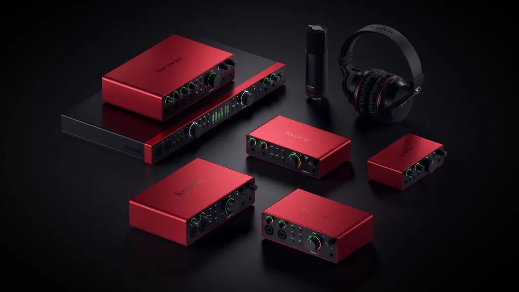
Audio Hardware coming to Arm64 Vendor-specific USB Audio / ASIO driver preview from Focusrite early in 2025 Vendor-specific USB Audio / ASIO driver preview from Steinberg/Yamaha in 2025
In-Box Support coming to Arm64 ASIO and low-latency USB Audio Class 2 driver previews mid 2025, in-box in Windows when complete MIDI 2.0 (Windows MIDI Services) previews in Windows Insider builds this November, in-box in retail Windows early next year.
From my own use and from working with others in the music industry, I know we need to have support for two major features on Windows for musicians to have a great experience:
Better APIs which support MIDI, including MIDI 2.0, with backwards compatibility with MIDI 1.0 APIs and devices. Our older MIDI stack hasn’t kept up with current needs, and needed replacing so that we can grow and innovate.
Full support for low-latency, high-channel-count audio, using standards already accepted by the industry
Pete Brown-Microsoft
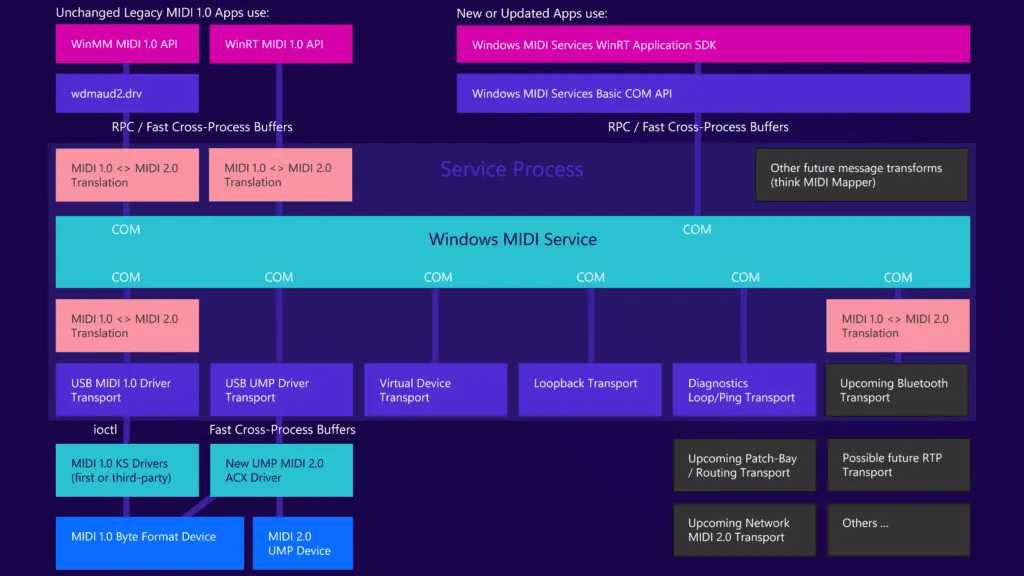
Windows MIDI Services: The New Windows MIDI Stack
Windows MIDI Services supports MIDI 1.0 as well as the MIDI 2.0 Universal MIDI Packet (UMP) standard. Together this provides compatibility with existing MIDI devices as well as the new MIDI 2.0 devices already in-market or coming soon (I have several MIDI 2.0 devices here in my studio).
MIDI CI, which bridges the gap between MIDI 1.0 and MIDI 2.0 UMP, is supported through normal SysEx support, and we recommend the use of open source cross-platform libraries which help with creating and parsing those messages.
Pete Brown-Microsoft
Backwards compatibility with the WinMM MIDI 1.0 API
The Association of Musical Electronics Industries (AMEI), the organization that oversees the MIDI specification in Japan, committed to funding the development of an open-source USB MIDI 2.0 Host Driver for Windows Operating Systems under a memorandum of understanding between AMEI, AmeNote Inc, and Microsoft.
AMEI is underwriting the cost and has engaged AmeNote Inc. to develop the driver because of AmeNote’s extensive experience in MIDI 2.0 and USB development. In addition, concurrent to this, Microsoft has also agreed to start development of a Windows standard open-source MIDI 2.0 API.
The driver and API will be developed in accordance with Microsoft’s quality control standards, and will be managed as a permissively licensed (MIT license) Microsoft open-source project. As a result, anyone can participate in the development as an open-source contributor in the future, or use the code in their own devices or operating systems. Because of this open source arrangement, continuous and timely improvements and enhancements to the USB MIDI 2.0 Host driver and MIDI 2.0 API are expected.
Here is a list of the AMEI companies supporting this work.
l AlphaTheta Corporation
l INTERNET Co., Ltd.
l Kawai Musical Instruments Manufacturing Co., Ltd.
l CRYPTON FUTURE MEDIA, INC.
l CRIMSON TECHNOLOGY, Inc.
l KORG INC.
l Educational Corporation Shobi Gakuen
l SyncPower Corporation
l ZOOM CORPORATION
l -SUZUKI MUSICAL INST. MFG. CO.,LTD.
l TEAC CORPORATION
l Yamaha Corporation
l Yamaha Music Entertainment Holdings, Inc.
l Roland Corporation
l Analog Devices, K.K.
For the full blog from Pete on the New Windows MIDI Stack, please click on the link below.
We’ve recently kicked off a project with Qualcomm and Yamaha to create a brand new USB Audio Class 2 Driver in Windows, with both WaveRT (our internal audio) and ASIO interfaces, following the latest standards for Windows driver development using the ACX framework.
The new driver will support the devices that our current USB Audio Class 2 driver supports, but will increase support for high-IO-count interfaces with an option for low-latency for musician scenarios.
It will have an ASIO interface so all the existing DAWs on Windows can use it, and it will support the interface being used by Windows and the DAW application at the same time, like a few ASIO drivers do today. And, of course, it will handle power management events on the new CPUs.
This driver will work with USB Audio Class 2 devices, so you can plug in your device, and get right to making music.
Finally, we’ll make the class driver source available to others on GitHub, just like we have with MIDI, so that any company creating their own USB Audio Class 2 drivers will be able to learn from how we handled events and also give us suggestions for how we could do better. It’s a two-way conversation.
Pete Brown-Microsoft
Announcing: Hardware-optimized USB Audio drivers on Arm64
Our new in-box driver needs to work well for all compliant USB Audio Class 2 devices. But some hardware developers are expert driver authors, and for years have known that if they write their own optimized drivers for their USB Audio Interfaces, even on other platforms with built-in drivers and low-latency APIs, they can achieve even better round-trip latency at the same levels of stability. Every millisecond counts!
Pete Brown-Microsoft
Focusrite – Native on Arm64
“Focusrite is targeting releasing native Arm64 drivers for all of its supported USB audio interface products in early 2025, bringing compatibility with all ASIO and non-ASIO applications running on the platform.”
Tim Carroll, CEO Focusrite Group
CEO Focusrite Group, President of The MIDI Association
Yamaha – Native on Arm64
Yamaha creates the Steinberg-branded USB audio interfaces, which are fantastic performers on Windows and loved by their customers. In addition to working on the in-box class driver for Arm64, they are going to release optimized device-family versions of their audio interface drivers for Windows on Arm, giving users of their devices the best of both worlds. We’re excited to see these drivers coming out for Arm64 in 2025!
Pete Brown- Microsoft
Announcing: New Musician-focused apps coming to Arm64
With the new MIDI stack and in-box ASIO, these three killer DAW apps, and two families of audio interfaces with optimized drivers for Arm64, we’re set up to help make the experience of creating music amazing on Windows. I am beyond excited for so many of these efforts to come together at this point in time. A huge thanks to all our hardware and software partners who have stepped up to help musicians and other audio creators on Windows.
Pete Brown-Microsoft
Cubase x Snapdragon: Redefining mobile music production
For the full blog from Pete on Make Great Music with Windows on Arm, please click on the link below.
At the MIDI Forum, there were a number of technology presentations and one of the most fascinating was from Robin Zhang about the open source software he developed called Digishow.
Robin runs a creators’ collective in a beautiful old building that used to be the home of the Lester School and Technical Institute. They get diverse people from different backgrounds (musicians, lighting, artists, designers) to work together and create unique pieces of art using Digishow.
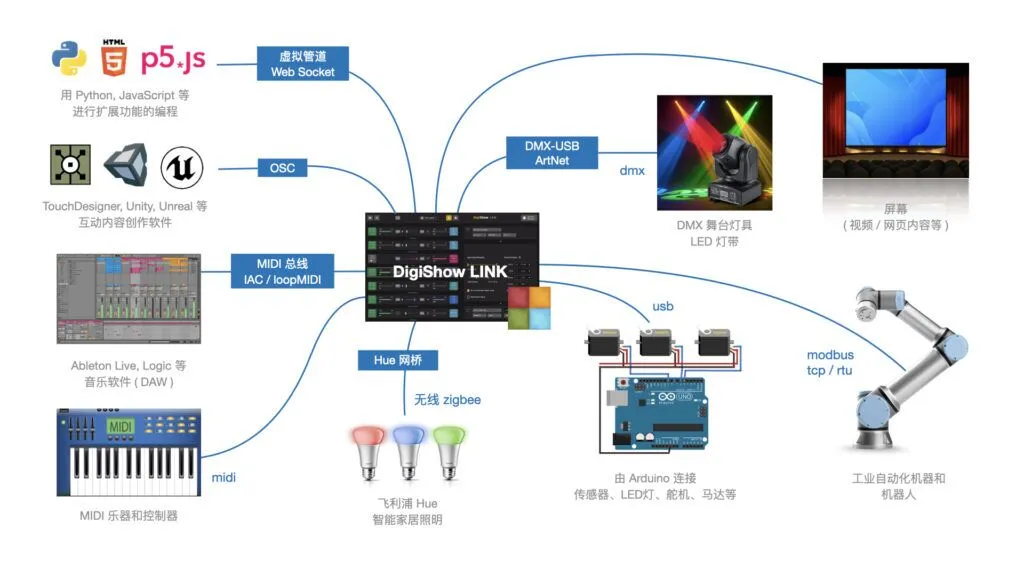
DigiShow is a lightweight control software designed for live performances and immersive show spaces with music, lights, displays, robots and interactive installations. It serves as an easy-to-use console for signal controlling, also enables signal mapping between MIDI, DMX, OSC, ArtNet, Modbus, Arduino, Philips Hue and more digital interfaces.
With using DigiShow LINK app, there are some scenarios assumed:
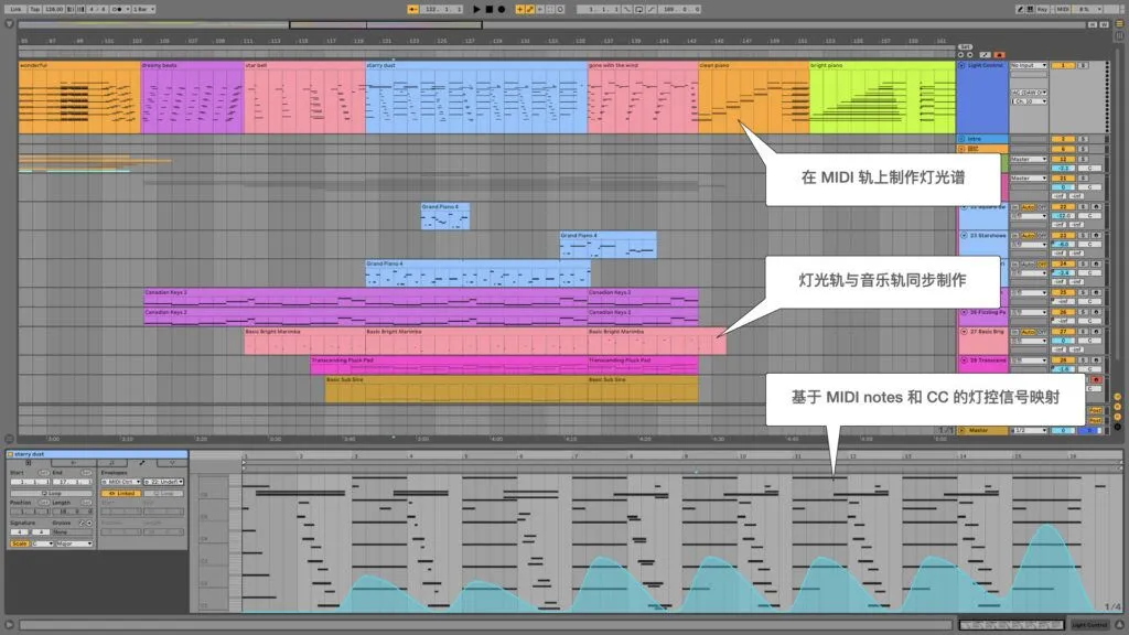
Producers: For live music or theatre performances, DJ or producers can arrange show lighting cues and stage automations on MIDI tracks alongside the music tracks in Ableton Live or other DAW. At the show, press the button on the Launchpad, the music loop and lighting effects will be instantly played in sync.
Ableton Live with tracks programmed for Digishow
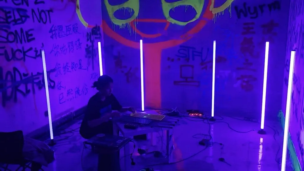
Picture of magnetic and MIDI demo with lightshow
Performers: When playing MIDI instruments like drums or keyboards, DigiShow can trigger dynamic lighting changes and even robotic movements by MIDI notes following the beat or the music. Sensors can also be added to acoustic or DIY instruments to automatically generate MIDI notes.
Artists and Designer: For building interactive art installations, the creators often need to make software that works with the hardware. DigiShow provides OSC, ArtNet, WebSocket pipes for inter-application communication. Designers can create their interactive content in some creative software like TouchDesigner, Unity 3D, P5.js and access the hardware easily through DigiShow. Developers can also program using Python or JavaScript to connect DigiShow and extend interaction logic.
Storefront Display programmed by Digishow and simulated in Touch Designer
Makers and Hobbyists: DigiShow is for all show makers as well as hobbyists with little professional skills. Make digital shows for your own party time, or just make your house into a mini ‘disneyland’.


