i search on paper... :
on midi din, there are two ouput voltages or juts one (i see this in a next time...) on midi din 4 and 5.
i understand probably interst of din 5 (uart, data midi), but :
what's object or intrest for din 4 ? there are no uart on this, is it only an electricity alimentation for the receiver with no data ?
thanks
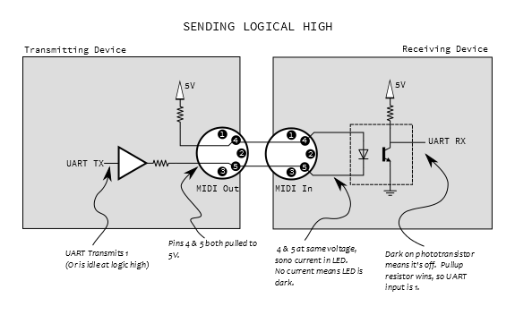
MIDI uses a current loop (mark = 0 mA, space = 5 mA). Two pins are needed to drive the required current through the receiver's IR LED. The three resistors (two in the sender, one in the receiver) are needed to limit the current to 5 mA; the resistors are distributed this way to make the connectors short-circuit tolerant.
The actual voltages at pins 4 and 5 are not really important. (However, some cheap interfaces omit the optoisolator and just measure the voltage at pin 5; in that case, pin 4 is not needed.)
The shield (connected to pin 2 at the sender) blocks electrical noise.
The current goes from pin 4 to pin 5. To transmit a 0 bit, the sender pulls pin 5 low. To transmit a 1 bit, the sender pulls pin 5 high, or leaves it open.

