Build a MIDI Controller with Arduino

Hi everyone! In this article I will teach you how to build your own Arduino powered MIDI controller. MIDI stands for Musical Instrument Digital Interface and it is a protocol that allows computers, musical instruments and other hardware to communicate. If you follow each and every step of this tutorial you will be able to make music with an Arduino!
What you are going to learn from this article:
- Chose the right components for this project.
- Sketch an interface with the right dimensions and build it.
- Read the circuit schematics and connect/solder every component to the Arduino.
- Chose the right software to connect the MIDI Controller with the DAW you are using.
- Mapping the MIDI Controller.
Make sure you watch the video because it´s more illustrative. Subscribe to my Youtube channel so you don´t miss out on new project and to help me grow!
Step 1: Gather All the Material
Here is a list of the material and tools we need to complete this project:
12 x Arcade Push Buttons
Material to build the case ( I decided to build a wooden case )
I chose the Arduino Starter Kit because this kit provides a lot of useful material for this project such as resistors and all the wiring and connectors. Also, if you are a begginer like me, other material with this kit can help you getting started with electronics
I bought the Arcade Buttons from the link above but if I were to buy again, I would buy THESE BUTTONS instead because I wanted to give a pattern to the interface and it was impossible with single colored buttons so I had to paint them.
Tools you will need:
- Hobby file
- Sand paper
- Screw driver
- X-acto knife
- Caliper
- Ruler
- Wood bits
- Spade bit
- Jumper wires
- Insulation tape
- Varnish
- Paint
- Wire stripper
- Wire cutter
- Saw
- Power drill
- Mini Axe Saw
- Dremel
- Super glue
- Soldering Iron
- Solder
- Soldering paste
Step 2: Sketching and Building the Interface
I highly recommend sketching your interface so you are sure of the dimensions you need to build the case.
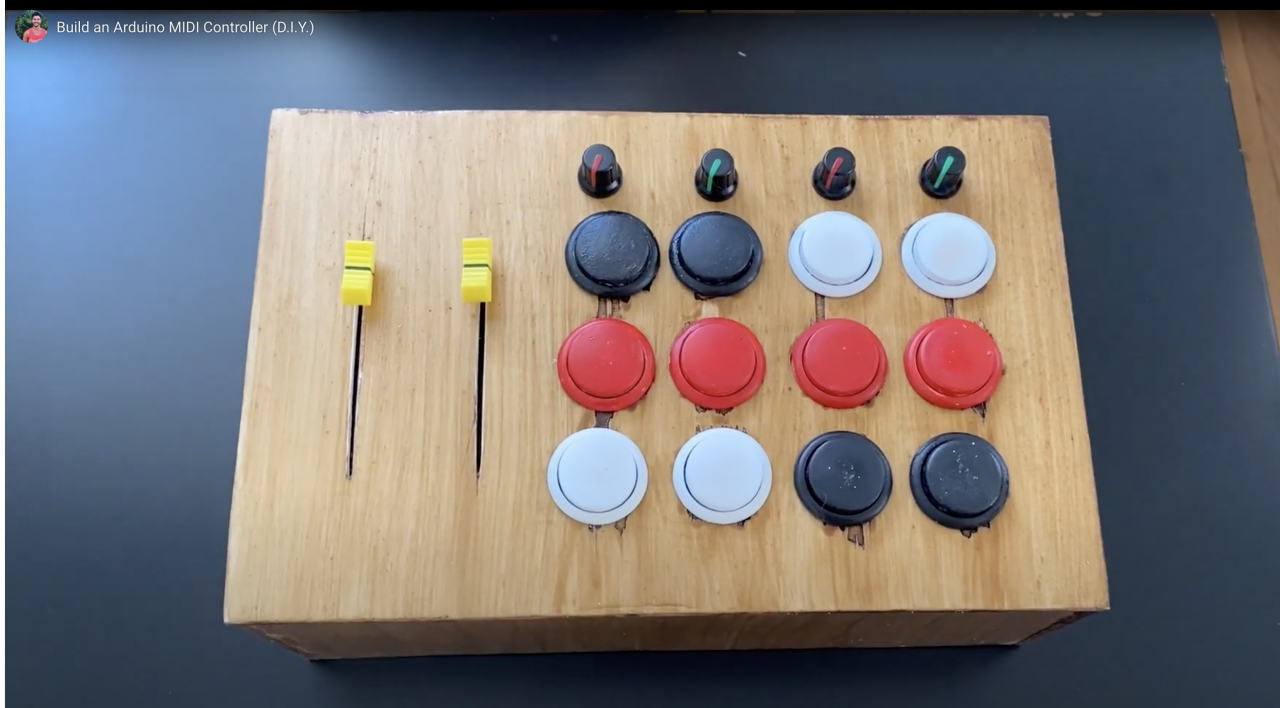
I projected my interface on a A4 sheet, using a pencil a ruler and a compass. You can see the result in the picture below. By sketching the interface, you get to know the dimensions you need to install all the components. My Push Buttons have a 29.7mm diameter so I am going to drill a 30mm hole to install it. Every hole is spaced by 10mm. Basically each circle center is spaced by 40mm (diameter = 30 + space = 10).
Pot Knobs have a 10mm diameter. It is recommended to drill with increasing diameter bits to make sure not to crack the wood. I also left a 10mm space between buttons and pot knob potentiometers.
And finally, the sliding potentiometers. From the data sheet I know their travelling distance is about 80mm. You should use a Dremel to open the slots to fit in the sliding potentiometers, a.k.a. FADERS. If you don´t have this specific tool you can always do it as I show on the video. Think about a slot with 80mm length and 3mm wide.
This was my COVID-19 quarantines project. I was determined to find a productive way to spend my time and the Arduino that was left in a drawer came to mind. I went to my local store to buy wood to make the enclosure and as I bought it I was told they weren´t cutting wood because of the lack of personnel and due to this whole self-isolating/lockdown. So, I decided to buy the wood and cut it at home with the material I had available.
After removing the splinters with sand paper and preparing the surface I applied varnish paint. Two coating were applied. After I chose a color to paint the enclosure. You can check the pictures to see the result!
Step 3: Circuit Diagram and Connections
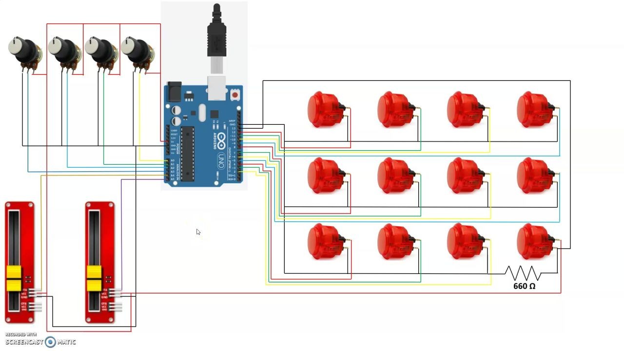
I decided to Illustrate the circuit diagram instead of drawing the conventional circuit diagram because it can get very confusing. I used several colors to separate jumper wires so you can understand where each wire belongs.
The chip used on the Arduino contains internal pull-up resistors, so there´s no need to wire resistors for each of the arcade buttons. This greatly simplifies the controller wiring.
All we need to do is choosing one leg of the Arcade Buttons to be the ground, the other will be power, which will be connected to one of the digital inputs on the Arduino board.
Faders have three legs, the first one (counting from the bottom) is the ground (-), second is power (+) and the third one is the signal.
For the Pot knob potentiometers its the following: left leg is ground (-), middle leg is the signal and right leg will be power (+).
The Arduino is going to be the brain of the MIDI Controller. It is going to send MIDI instructions to the software, depending on the button pushing input.
The interior is going to get very messing because of all the wires, I would advice you to structure the soldering process. For example, I decided to solder all the ground wires first, the power and finally I soldered the signal jumper wires.
After soldering and connecting all the pins to the Arduino board, we can close the enclosure. Have a look at the pictures to see the final outcome!
Step 4: Softwares and Programming
You will need three pieces of software in order to be able to make music with your Arduino.
First, you need to download the Arduino IDE software to start writing your own code and upload sketches to the Arduino board.
Secondly, you need to download the LoopMidi software which is essentially a virtual midi cable.
Finally, to send your midi serial data to the LoopMidi software you will need the Hairless Midi to Serial Bridge software. This software is great to let you know if your wiring is correct because you can see the data flux exchanged between the MIDI Controller and the Hairless Midi Serial.
First step is opening the Arduino software and the code I am attaching to this Instructable (called MIDI_Controller). Credits are given to the Author Michael Balzer. You should not need to modify the code. Just verify the sketch which is kind of like a “debug” and when you get the message that the compilation is complete you can send it to the Arduino board.
Then head to the LoopMidi and chose a new port name. Once you chose one just press the plus button which will create the new port. After this step open the Hairless Midi Serial Bridge and start by selecting the MIDI In port that you have just created. Then select the same MIDI Out port. Finally chose the serial port of your computer (usually COM#). Congratulations, you have just enabled your MIDI Controller to communicate with the computer!
Step 5: Mapping the MIDI Controller
If you got this far Congratulations!!! You are just a few steps from start making music with Arduino and playing with your MIDI Controller!
Now you want to head over to your DAW (Digital Audio Workstation) and set the settings to recognize the external input which is your MIDI Controller. The example I am providing is with Ableton Live. You need to go to
Options >> Preferences : The Input Midi Port should be the one you defined earlier and you need turn the track and remote toggle button on.
Now if you press any button on your MIDI interface you should see a light flashing at the top right corner of the DAW which means the software is receiving the midi signals you are sending! To map the MIDI Controller just click on the “MIDI” button and the DAW color should turn purple. Now click over any slot and then press any button, you will see a note/control associated to it which means the button is mapped!
And you are done! Congratulations! Great project and great job! Let me know if you made it!


